In this post I’ll show you how to implement a marquee running on an Arduino Pro Mini (5V). The project uses a slightly adapted version of the C source we developed for running the same project based on a Raspberry Pi 3B+. The main changes werd applied due to the two function void setup() and void loop(), which perform the application setup and contain our program’s main loop.
Motivation
The motivation for this project is to create a more portable solution of our marquee project, which I initially developed using a Raspberry Pi 3B+. Since the Arduino is a Microcontrolle, we do not need to have a whole Operating System running in order to operate the LED Matrix Display and present a cool scrolling text. Our sourcecode is directly compiled for the ATmeg328P and uploaded to the device.
This way we end up with a device having a much lower power consumption since it runs just a few components instead of a complete PC, with graphic card, sound card, microSD card reader, WIFI-interface, ethernet interface, bluetooth Interface, H.264-encoder/decoder and the like.
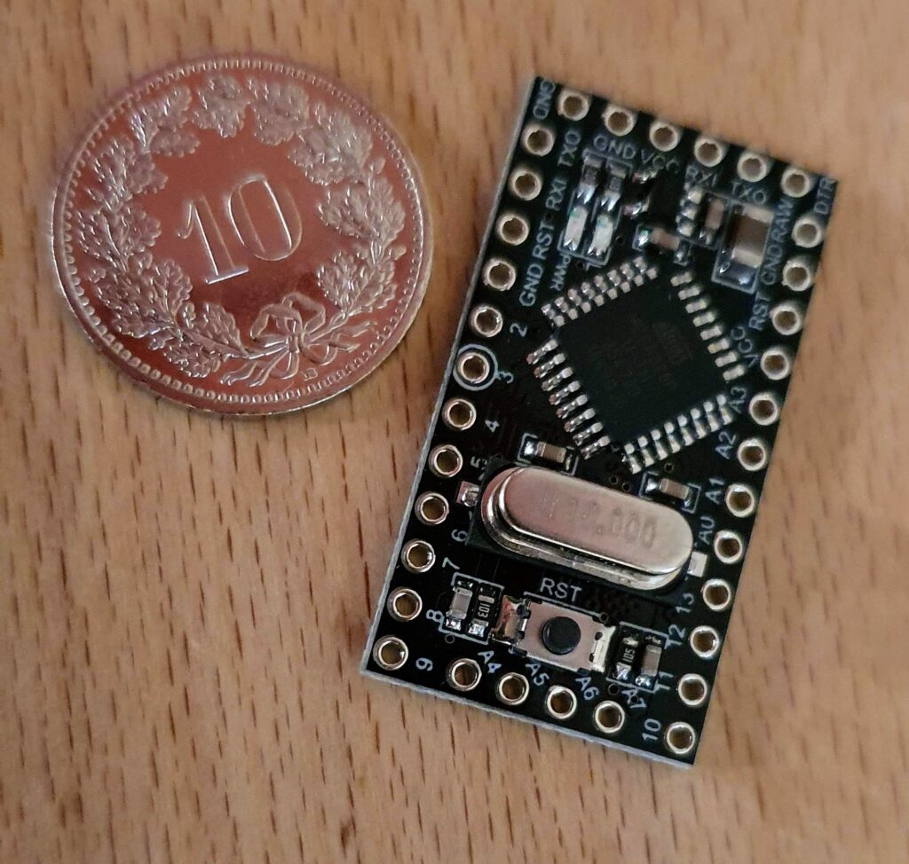
Another motivation is the size of the device. Compared to the Raspberry Pi B3+, the Arduino Pro Mini is deciderably smaller:
What you need
- Arduino Pro mini ATmega328P (5V) compatible board, i.e. buy here
- Mini USB UART FTDI Programmer 3.3/5V USB Serial, buy here
- An apropriate cable to connect the UART FTDI Programmer to your PC; in my case I needed a Mini-USB 2 USB cable)
- LED 8×8 Matrix Display, buy here
- C sourcecode to be compiled / uploaded to the microcontroller, get source here
- 9 V battery and a snap-clip connector, get the connector here
- Soldering station, soldering wire
- A PC running the Arduino IDE, get the software here
Of course you can also buy an Arduino Nano instead, which already provides the Mini USB connector, so you would not have to buy the Mini USB UART FTDI Programmer. However, the less hardware provided on the Arduino board, the less power will be consumed for unnecessary tasks, so – especially when you intend to run your Arduino on battery power – it makes sense to have the minimal hardware configuration suiting our needs. That’s why I decided to go for the Arduino Pro Mini in combination with an externa UART FTDI Programmer which can be connected via USB / Mini-USB to my PC.
Connect 8×8 LED Matrix Display to Arduino Pro Mini
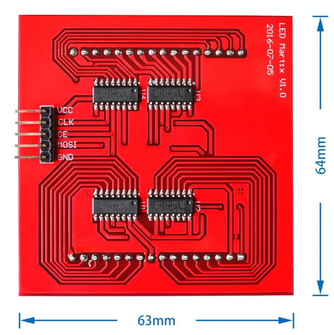
To connect the LED Matrix Display to your Arduino, check the lables on the Arduino Board as well as on the Matrix Display and follow the information provided in this table (ingore the Raspberry Pi-mapping beneath). To test if everything is working, you can first plug the cables coming from the LED Display to a pin-header usually contained in the delivery and just stick the header onto the board. Later, if everything is working as expected, you can solder the cables to the board or only solder the header to the board, if you want to have the possibility to reuse your Arduino for other projects.
| Raspberry Pi | 8×8 RGB Matrix | Arduino |
|---|---|---|
| 5V | VCC | 5v |
| BCM GPIO 11 | CLK | Pin 13 |
| BCM GPIO 8 | CE | Pin 10 |
| BCM GPIO 10 | MOSI | Pin 11 |
| GND | GND | GND |
Upload Preparations
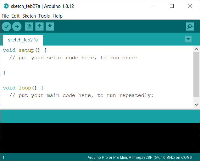
After having connected the LED Display to your Arduino, first install the Arduino IDE on your PC. You can download it here. Alternatively you can also just run the Arduino Web Editor, which you can use to program your devices without the need of any installation. If you are yet an unexperienced programmer, you’ll find lots of introductory material provided on the arduino website. I installed the binary version on a windows laptop, which after starting looks as follows:
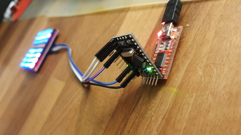
Then connect your Arduino Pro Mini with an apropriate USB cable (in my case it’s a Mini-USB / USB cable) to your laptop. Make sure to stick the Arduino the right way into the UART FTDI Programmer. Initially I connected them the wrong way round having the effect of not being able to upload my code to my arduino. The following picture shows the correct configuration:
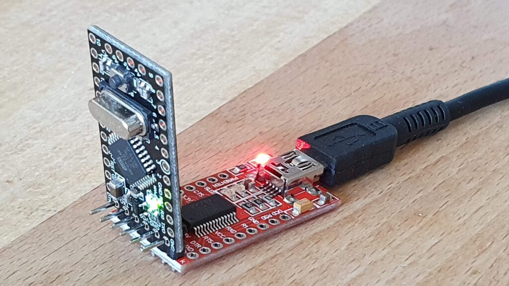
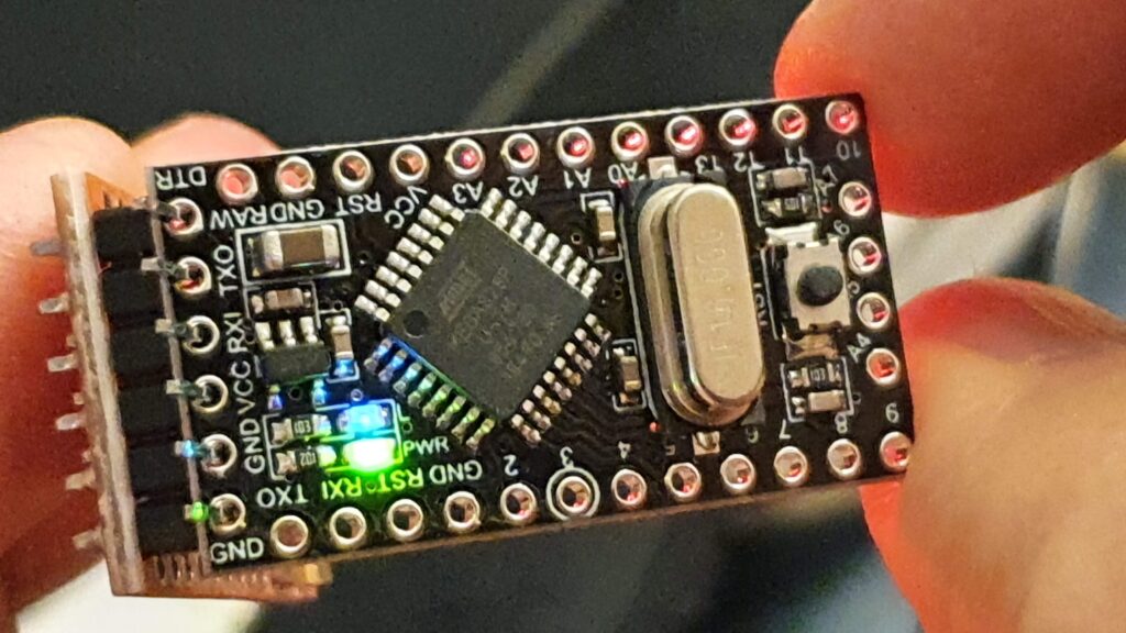
Note: There is probably a LED on the UART FTDI Programmer (red) but for sure one on the Arduino board (green) indicating operation (see picture above). If you cannot see these LEDs lighting up, check your cable connection and make sure you connected the parts together in the correct way.
Since now you have connected the Arduino to your PC, you can try to upload a simple demo script using your Arduino IDE or the Arduino Web Editor. In order for the upload to wor, you need to make sure to have the correct model selected in the ‘Tools/Board’ menu. Select board “Arduino Pro or Pro Mini”. In the Processor Menu choose the processor type of your device, “ATmega328P (5V, 16 MHz)” in my case.
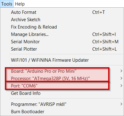
To determine the port is a bit trickier. Where as in the hardware-overview I found the device, there was no hint to determine which COM-Port the device is connected to. The easiest way to determine the COM-Port number your Arduino is connected to is just to try to upload some code. If it doesn’t work, most likely you have chosen the wrong COM-port.
The Arduino – “Hello World!”
Now it’s time to upload some code for the first time to your device and test it. The Arduino IDE comes with a set of sample-programs ready to compile and upload.
- From the ‘File’-menu choose “Examples/Basic/Blink”
- Click the ✓ Icon in the navigation bar of the IDE to compile the source of the Blink-example. In this step no connection to the Arduino is needed.
- Choose a COM-port from the “Tools/Port” menu you want to use to upload code to your Arduino
- Click the → Icon in the navigation bar of the IDE to try to upload your code
- Repeat the last 2 steps with varying COM-ports until you succeed uploading your code
If the ‘blink’-code has successfully been uploaded to the device, you should see the green LED flashing.
Upload the Marquee Code
Now as you managed to compile a sample program and upload the machine code to your Arduino, we take it one step further and repeat the last step with our marquee source code:
- Get the arduino version of my marquee source code here
- Open an empty scratch within your Arduino IDE and paste the code
- Modify the message text to your personal message to be displayed
- Compile it
- Upload the code to your Arduino
After uploading the code, your Arduino should start immediately displaying the scrolling text on the LED Display. If everything is working fine, you’re ready to take the last step to make your solution portable!
Attach the Battery
If you want to run your marquee indipendently from your computer or a current socket / power adapter, you might want to attach your device to a battery. To connect the Arduino Pro Mini (5V) to a 9V Battery, you have to connect the 9V Battery-Clip on the correct pins. Have a look at the following picture:
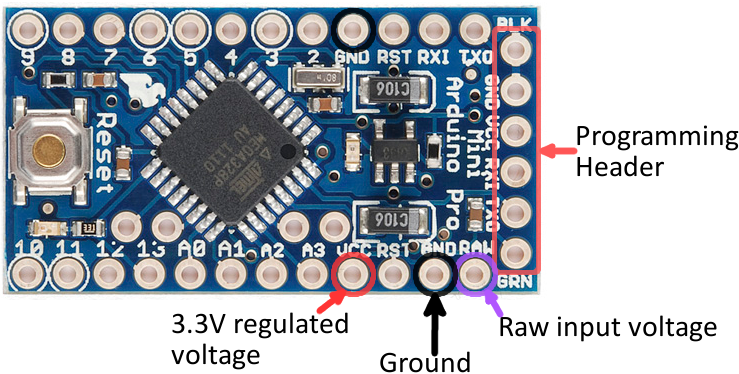
As you can see, we need to connect the battery to the ‘GND’ and ‘RAW’ pins. The red wire (positive pole) has to be connected to the ‘RAW’ pin, the black wire (negative / ground pole) to the ‘GND’ pin.
How to reduce power consumption of the Arduino Pro Mini
There are even mods to further reduce power consumption of an Arduino Pro mini available in the Arduino – Scene. As can be read here and in other web-resources, there are two most discussed measures in order to reduce power-consumption of Arduino Pro mini:
- remove the power LED
- remove the voltage regulator
On the website of the home automation community you can find the following pictures and additional information how to remove these two components.


I did not try to remove components on my devices. However I would not remove the regulator in combination with my design where we are running the board on a 9V battery.
There are even libraries to put Arduino to sleep and to further reduce power consumption until a defined interrupt occurrs. We will not make use of that for our project and rather focus.